
Peter McCombe, Ashish Diwan, and Hans-Joachim Wilke
INTRODUCTION
Movement of the spine is important for all activities of daily living, work and leisure. Spinal movement is essential to change posture to adapt the spinal curves, particularly in the sagittal plane, to bear a load in the most energy-efficient manner. Loss of movement may also contribute to adjacent segment degeneration after spinal fusion, whether surgical or spontaneous. It is therefore intuitively desirable to want to maintain “normal” movement in surgical procedures of the lumbar spine. If this goal is accepted, one must ask: what is “normal” movement, and how can it be simulated durably and safely with an implant? The biomechanical disciplines of kinematics and kinetics can help answer these questions.
Kinematics is the study of the path taken in space by a moving object, without regard for the forces that cause the movement. The most important kinematic parameter for spinal movement is the description of the position and movement (if any) of the centre of rotation (COR). The position and movement of the COR for each spinal level provide a concise description or a "kinematic signature" of the movement.
Kinetic analysis is the study of the relationship of the applied forces to the movement that is created. The most important kinetic measurement is the load-displacement curve. The shape of the load-displacement curve provides a concise description or “kinetic signature” of this relationship.
It follows that the biomechanical goal of a motion-sparing implant is to approximate, in situ, in a safely and durably, the kinematic and kinetic signatures of the intact motion segment.
KINEMATICS OF LUMBAR SEGMENTAL MOVEMENT
Motion at an individual spinal segment can best be understood by considering one of the vertebrae to be fixed (usually the lower), with the other vertebra moving in the frame of reference of the fixed vertebra. If the moving vertebra were not attached in any way to the fixed vertebra, it would be free to either arbitrarily translate or rotate within this frame of reference.
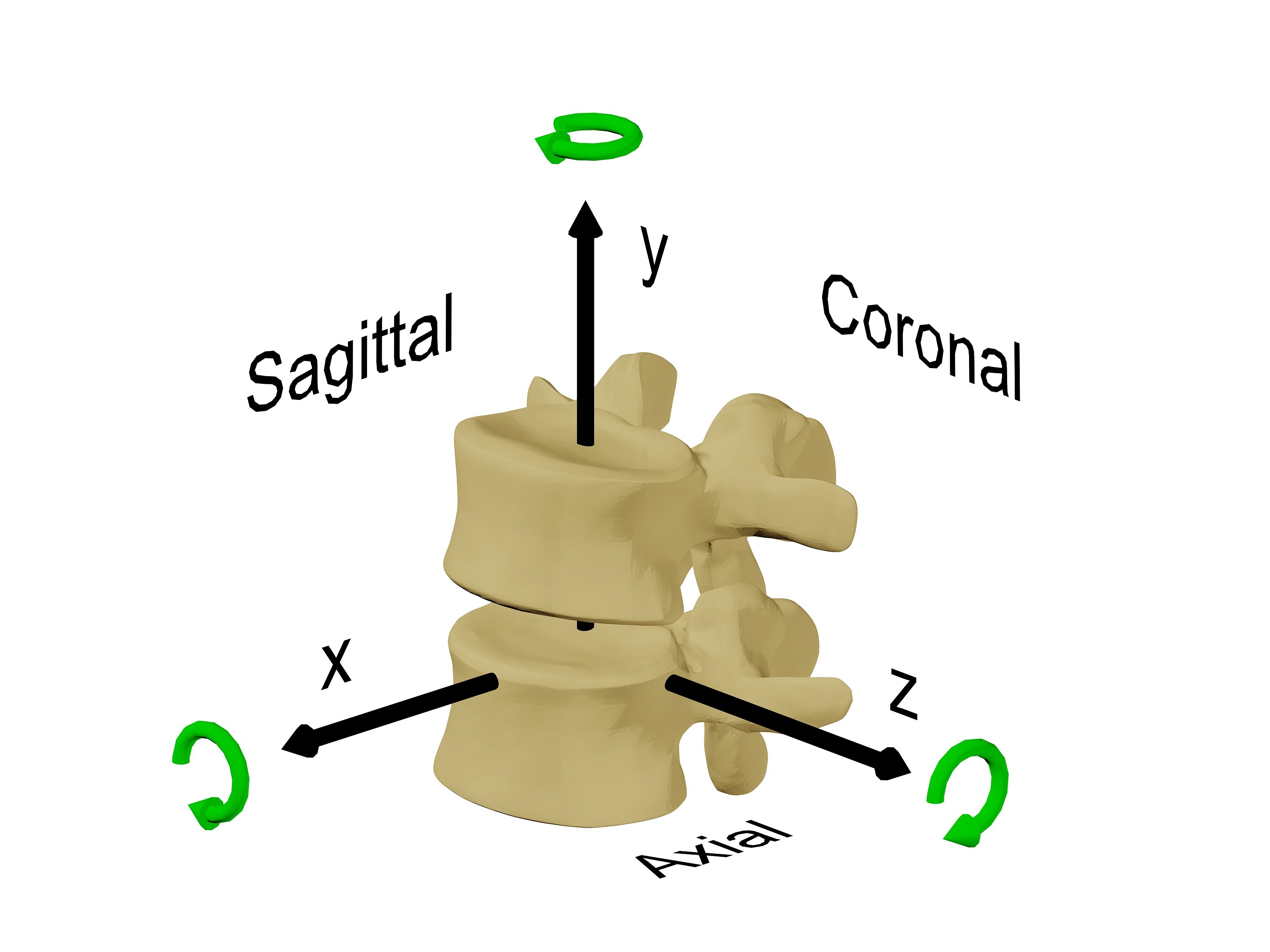
Totally unconstrained motion in three dimensions is said to consist of six degrees of freedom (DOF): three each for translation along an X, Y and Z axis and three each for rotation around the X, Y and Z axis (Fig. 6-1). It is common to consider this movement in the two dimensions of one of the primary anatomical planes, such as the sagittal plane, that is displayed on the lateral x-ray. In this situation, there are said to be 3DOF, two of independent translation along an X and Y axis and one of rotation around a Z axis. The motion segment, however, has the soft tissue attachments of the ligaments, intervertebral disc, facet joints and muscles between the stationary and the moving vertebra. These soft tissues constrain the movement that is possible to the commonly observed path in the sagittal plane of flexion and extension. The notion of rotation in a plane must, by definition, consist of rotation about an axis that is orthogonal (at right angles to both axes) to that plane. If a vertebra is observed to rotate, then it must rotate about a unique axis that, along with the angular displacement, fully describes the change in position. This axis is the “axis of rotation” (AOR) (Fig. 6-2) or the “instantaneous axis of rotation” (IAR) if the rotation is considered at a point in time. It is common to consider the point where this axis penetrates the plane in which the movement occurs as the “centre of rotation” (COR). In practice, the terms COR and IAR are used interchangeably.

The motion of flexion and extension can be simply described as the AOR being orthogonal to the sagittal plane. However, axial rotation and lateral bending are more complex motions with coupled movements — meaning that rotation in one anatomical plane is also associated with rotation in at least one other anatomical plane. The problem of coupled motion is really a problem of the frame of reference used; it is usually possible, when coupled motion is present, to define another unique three-dimensional axis that is inclined to the usual anatomical planes such that the motion is fully described by rotation around that axis. The AOR of axial rotation and lateral bending in the lumbar spine are usually inclined to the anatomical axes. Figure 6-3 shows an axis of rotation that approximates the AOR for coupled axial rotation and lateral bending.

Calculation of the Center of Rotation
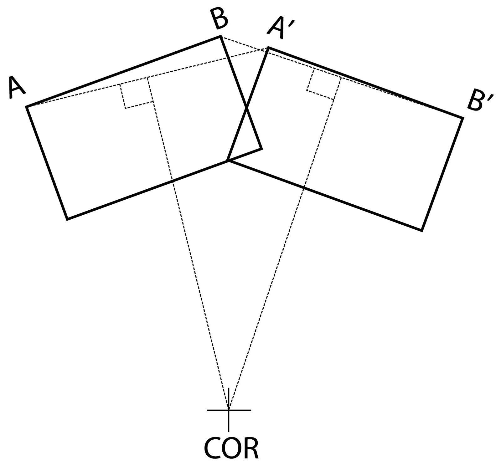
The COR is usually calculated graphically as the intersection of two perpendicular bisectors of lines joining the starting and finishing positions of the same points on the object (Fig. 6-4). This calculation is very sensitive to accurate identification of points on the vertebra, which is prone to significant error. The point identification error is highest in clinical x-rays, less in cadaver testing with accurate three-dimensional trackers applied to the vertebra and least with finite element analysis (FEA) studies. FEA studies have a zero measurement error, though such studies may have other errors with model validity. Pearcy and Bogduk found, in their in vivo study, a range of motion of fewer than five degrees produced an unacceptable COR error.1 Because of the difficulty with the calculation of the COR with small angular displacements, it is usual with conventional in vivo measurement techniques to make the calculation over as large as possible an angular displacement, usually the entire range of motion. The average COR, calculated over the full range of motion, is the best single kinematic “signature” of a motion segment. However, the average COR may not fully reflect the actual motion if the position of the COR changes when the motion used for the calculation is split into smaller segments. When calculating the COR using a smaller angular displacement than the total range of motion, the term instantaneous axis of rotation (IAR) may be more appropriately used instead of COR. When using multiple smaller angular displacements for measurement, the most accurate kinematic signature is the movement and trajectory of the IAR.
For out-of-plane coupled movements, the centres of rotation can still be calculated in the plane of interest, though this will not fully describe the movement. For a more accurate representation of the motion, the helical axis of motion (HAM) is often used. Calculation of the HAM is complicated;2 however, it provides a useful summary of the movement by defining an axis about which the moving vertebra can rotate and along which the vertebra can translate.
The Average Centers of Rotation on the Lumbar Motion Segments
Several investigators have studied the in vivo locations of the IAR for sagittal flexion and extension movements of the lumbar motion segments.
Pearcy and Bogduk identified the mean location for the IARs, in ten young asymptomatic males, to lie just anterior to the posterior third of the disc and just below the superior endplate of the inferior vertebra for the L2-3, L3-4 and L4-5 levels. At L5-S1 the IAR was shown to lie in the posterior third of and within the disc space.1
Yoshioka et al. measured the location of the IAR in 61 senior high school students.3 While the size of the 95% probability ellipses for the IARs was larger than those found by Pearcy and Bogduk, the mean locations appear very similar or marginally anterior (at L4-5 and L5-S1).
White and Panjabi4 described the location of the COR of lateral bending as being on the left side of the disc for right lateral bending and the right side of the disc for left lateral bending, whereas the COR for axial rotation to both the right and the left was found centrally within the disc.
Movement of the Instant Axis of Rotation
While radiographs taken at the start and end of movement can be used to determine the location of the COR for the overall range of motion, the viscoelastic nature of the disc, the laxity of the facet joint capsules and the constraining effect of the facet joints themselves will mean that not all phases of that motion will necessarily occur about the same COR. Gertzbein et al.5 demonstrated, using an in vitro study of the L4-5 segment of lumbar spines, that the location of the instantaneous axis of rotation (IAR) moves during flexion and extension movements within a range he called the centrode.
Schmidt et al.6 studied the movement of the IAR during flexion and extension in a finite element model and found that the IAR moved anteriorly with increasing flexion, while the IAR moved posteriorly with increasing extension. In the same study, the IAR of lateral bending was shown to lie almost in the midline in the centre of the disc space with small loads, though it moved laterally and superiorly, to the side of the lateral bend, with increasing loads. The axial rotation IAR was found by Schmidt et al. to lie almost in the centre of the disc in the axial plane with small loads. However, it moved posteriorly towards the facet joint on the side opposite the rotation with increasing loads. Rousseau et al.7 showed in vitro that the IAR of L5-S1 moved forward when the specimen moved from extension to flexion followed by a superior movement during movement to full flexion. It was considered that a restraining sliding movement of the facets caused the end flexion range vertical movement of the IAR when they achieve full contact in flexion. Zander et al.,8 in a finite element study of the lumbar spine, calculated the HAM for flexion-extension, axial rotation and lateral bending. The penetration of the helical axes through the anatomical planes gave IAR’s that were consistent with the findings of Schmidt et al.6 The direction of the helical axes provided insight into the coupled motions that occur with axial rotation (coupled ipsilateral bending and flexion) and lateral bending (minimal). The orientation of the HAMs in a cadaver study by Kettler et al.9 is mostly in agreement with the FEA study of Zander et al.8. However, Kettler noted considerable variability in the HAM positions.
The kinematic behaviour of the lumbar spine in flexion-extension is best summarized by an average COR in the posterior half of the disc. The COR lies somewhat inferior in all discs except L5-S1, where it lies below the S1 endplate. The movement of the IAR during flexion-extension is in the general direction of posterior to anterior during extension to flexion and anterior to posterior during flexion to extension. The kinematics of lateral bending and axial rotation are more difficult to summarize because of difficulty in succinctly describing coupled movements. However, the IAR for axial rotation and lateral bending are different for right and left rotation or bending and lie initially within the disc on the side to which the vertebra rotates. There is, however, considerable variation between individuals and also between different anatomical levels.
The implication for lumbar disc arthroplasty design is that a lumbar prosthesis should enable a posterior COR for flexion-extension, which has some ability to move. COR movement is needed to simulate the normal segmental IAR movement, to adapt to different individuals and different spinal levels and to achieve different CORs for right and left lateral bending and axial rotation. Failure to fulfil this design goal will lead to conflict between the mechanism and the patient’s motion segment kinematics, leading to abnormal stresses and strains. The test of the ability of a prosthesis to avoid these abnormal stresses and strains is an ability to demonstrate near-physiological COR behaviour in the laboratory.
KINEMATICS OF LUMBAR DISC ARTHROPLASTY
The final kinematic behaviour of an implanted disc arthroplasty depends both on the inherent kinematic properties of the implant, which define possible movements outside a functional spinal unit (FSU), and the interaction of the prosthesis with the further constraints that the soft tissues of the FSU provide. It is instructive to consider both separately.
Inherent Kinematics of Disc Replacements
In the same way that soft tissues and facet joints constrain some of the possible DOF of a motion segment, the addition of a mechanism will, of course, constrain some of the otherwise possible DOF of the prosthesis. In this sense, the mechanism “constrains” the number of degrees of freedom that are possible, with different mechanisms permitting a different number of DOF. It follows that a rational kinematic classification for disc replacement mechanisms is to specify the number of permitted DOF. Those mechanisms with the least possible DOF would be the most “constrained”, and those mechanisms with the most DOF would be the least “constrained.”
Furthermore, the number of DOF will determine what COR is possible. In the most “constrained” case (3DOF) only a single point COR is possible, with mechanisms with more DOF allowing more than one COR.
Types of prosthesis mechanisms
The basic types of prosthesis mechanisms are ball and socket, dual articulating core and flexible core (Fig. 6-5 and Fig. 6-6).


Native prosthesis degrees of freedom
Rotation is unconstrained in all total disc arthroplasties (TDAs) — they are all capable of independent rotation about all three axes (x, y and z) in 3D space. However, not all TDAs permit independent translation along at least some of the three axes. It is the capacity for independent translation that is the main kinematic difference found among the TDAs, and it carries significant implications for the mobility of the prosthesis COR during FSU movements. The main difference between the various types of TDA is whether or not there exists a constraint over translation along the x (the antero-posterior axis) or the z (lateral translation) axis (Fig. 6-1). This theory has been proposed by Huang et al.10 the definition of a constrained TDA is simply one that has no capacity for translation independently of rotation. Disc arthroplasty devices should, therefore, be classified as either constrained or unconstrained devices.
Constrained devices
Constrained devices permit rotation only around a fixed COR, such as a ball and socket articulation. A ball and socket articulation have three degrees-of-freedom (rotation in each of the three planes). Currently available examples include ProDisc-L (DePuy Synthes Spine, Raynham, MA, USA), Maverick (Medtronic, Memphis, TN, USA) and FlexiCore (Stryker Spine, Allendale, NJ, USA).
Unconstrained devices
Unconstrained devices permit independent translation in addition to rotation and may have up to six degrees of freedom. Unconstrained devices include:
- A dual articulating mobile core device that is constrained to permit independent translation in the antero-posterior direction only, such as the Activ L disc (Aesculap Implant Systems, Center Valley, PA, USA), with 4DOF. A ball and trough device is available in the cervical spine in the form of the Prestige disc (Medtronic, Memphis, TN, USA). This mechanism also allows only anterior-posterior translation and also has 4DOF.
- Dual articulating, mobile core devices such as Charite (DePuy Synthes Spine, Raynham, MA, USA), Kineflex (Southern Implants, Irene, Gauteng, South Africa) and Mobidisc (Zimmer Biomet, Warsaw, IN, USA). These mechanisms allow independent anterior-posterior translation and have 5DOF.
- Elastomeric polymer blocks fixed to the prosthesis endplates such as the LP-ESP disc (FH Orthopaedics, Heimsbrunn France), the Cadisc L (Ranier Technology, Teversham UK), and those with flexible, partly articulating cores such as the M6 disc (Spinal Kinetics, Sunnyvale, CA USA). These prostheses allow independent vertical translation as well as independent anterior-posterior and lateral translation and have 6DOF. (See Figure 6-6.)
Mechanism of translation
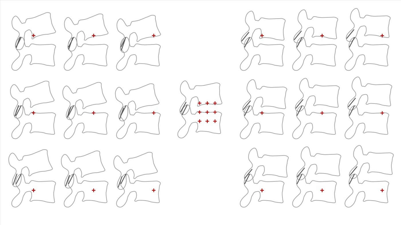
In dual articulating core prostheses of either 4DOF or 5DOF, there are many combinations of positions of each of the two articulations. Antero-posterior translation is achieved by producing just the right combinations of movement at each of the two independent articulations. By varying the ratio of movement at each of the articulations, within their limits, translation is possible with any fixed angle of flexion-extension (Fig. 6-7). In the 4DOF Activ L disc, there is a sliding biconvex core with a large radius on the bottom articulation that is constrained to permit only flexion and extension and a spherical top articulation. The net effect is to allow translation only in the sagittal plane (antero-posterior) and unconstrained rotation around all other axes. In fixed polymer block devices, there is no articulation; therefore, translation depends on the elastic deformation of the polymer block.

Vertical compression
Some prostheses can undergo, in addition to rotation and translation, axial compression. This movement involves vertical translation along the y-axis (Fig. 6-1) by compression of an elastomeric core. All prostheses that are capable of vertical compression can also translate and rotate; therefore, they have 6DOF. Examples of prostheses that have 6DOF include the M6 disc, the Cadisk and the LP-ESP disc. A complex design is, however, required to have physiological stiffness in both axial compression, rotation and translation in a non-articulating prosthesis that relies on polymer deformation. A single homogenous block of polymer that is roughly disc-shaped and has the appropriate stiffness to allow physiological flexion and extension will not have sufficient stiffness in axial compression. The LP-ESP disc achieves this functionality with a complex combination of a central core of silicone gel surrounded by polycarbonate urethane fixed to titanium endplates with various pegs and caps extending into the polycarbonate urethane and the central core.11 The M6 disc accomplishes this by having a polymer core that is sufficiently stiff to resist axial compression, though it is not fixed to the end plates, presumably allowing some motion during flexion-extension by articulation. The stiffness of flexion-extension is enhanced by an artificial annular structure. The Cadisk is a monobloc polymer design though the material properties of the polymer changes slowly between the centre and the periphery.
Kinematics of Implanted Disc Replacement
During rotatory movements
Constrained TDAs
As a constrained prosthesis cannot translate, independent of rotation, the trajectory of the moving component of the prosthesis (i.e., its upper component) is entirely dictated by the COR – in this case, the centre of the ball. When a constrained prosthesis is implanted into an FSU, the mechanism will attempt to guide the FSU’s movement.
If the COR of the constrained prosthesis exactly matches the COR of the FSU, then the trajectory of the FSU will be the same as it was pre-implantation. During movements of the FSU under these ideal circumstances, the adjacent soft tissues will undergo length change and change in the apposition of the facets that are identical to those occurring in the non-pathological FSU, causing a minimum strain on the FSU. It follows that, if the COR of the prosthesis does not match the FSU COR, the attempts of the prosthesis to guide the trajectory of the moving vertebra will, if it is successful, lead to abnormal FSU soft tissue strain. Depending on the nature of the mismatch, the facets may either be unloaded or overloaded.
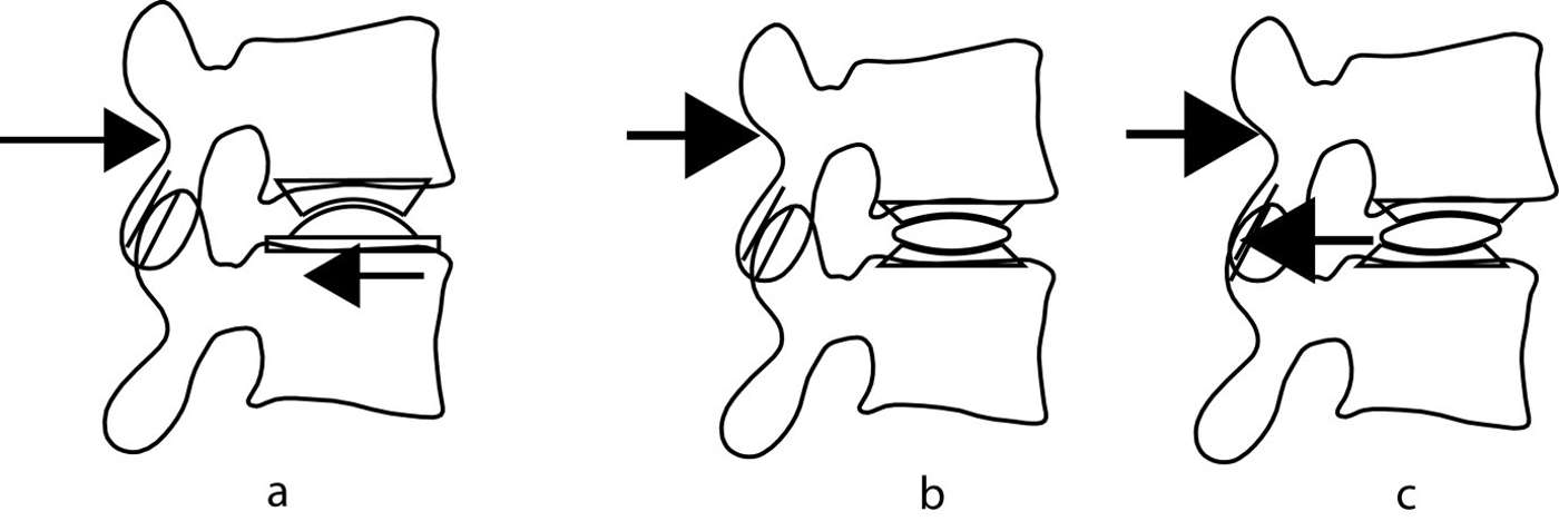
On the other hand, if the prosthesis is unable to guide the FSU because the strains are too large, the observed COR will substantially deviate from the fixed COR of a constrained ball and socket joint. In these circumstances, there must either be movement at the bone-prosthesis interface or some form of distortion or disruption of the prosthesis mechanism (Fig. 6-8). In an extreme case of mismatched CORs, dislocation of the prosthesis may occur.
The fundamental properties of a constrained prosthesis are:
- the prosthesis has a fixed COR;
- translation, independent of rotation around the COR cannot occur; and
- the prosthesis guides the spinal segment.
Unconstrained TDAs
All unconstrained prostheses can translate, in at least the antero-posterior direction, independently of rotation. Consequently, the upper vertebra is also free to translate, independent of rotation, and for any given rotation, several final positions are possible (Fig. 6-7). Because the prosthesis lacks an internal constraint for this movement, a constraint must be supplied from outside the mechanism to select the final, required position. This constraint is applied by the tension in the ligaments and annulus and by the facet joints.
The main consequence of the lack of constraint is that, unlike a constrained device, the FSU guides the prosthesis during movements and the prosthesis has more ability to adapt to the FSU’s natural COR. Consequently, the facet joints are less likely to be overloaded during flexion-extension movements, and there is liable to be less strain in the soft tissues than for a constrained device.
The fundamental properties of an unconstrained prosthesis are:
- the prosthesis is capable of adopting different CORs;
- translation that is independent of rotation can occur; and
- the motion segment guides the prosthesis.
COR mismatch and facet load
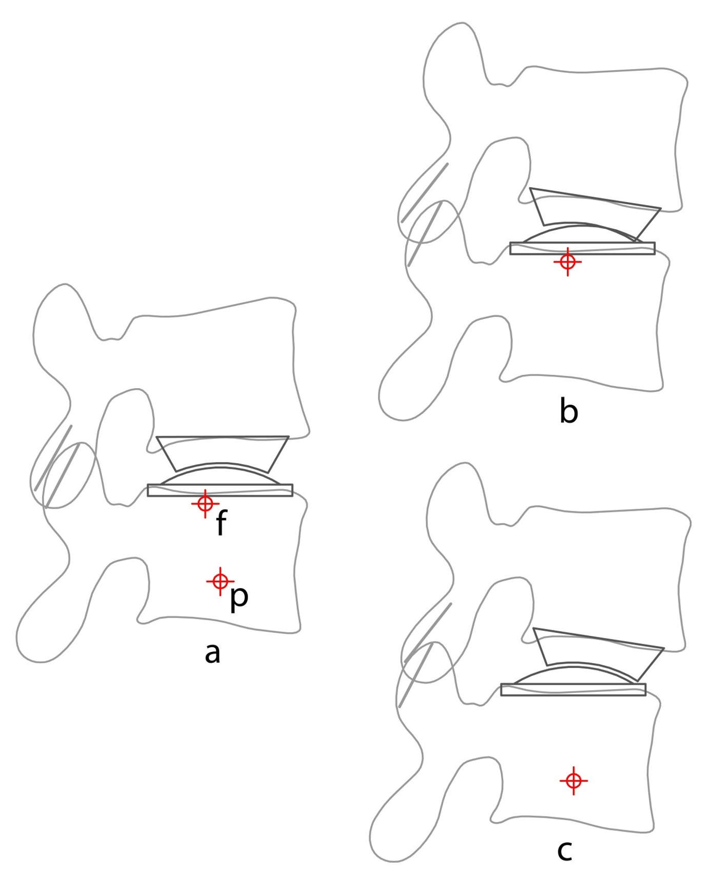
Regardless of whether a TDA is constrained or unconstrained, tension is created in the system when the prosthesis COR does not match the COR of the FSU. While this situation more readily occurs in a constrained prosthesis which cannot vary its COR, it can also occur in an unconstrained prosthesis as its capacity to have a variable COR is somewhat limited. Apart from causing soft tissue strain, COR mismatch also causes the facet joints to either impinge or distract. This change in facet loading may be important in the development of the facet degenerative changes that have been widely reported.12 The position of the prosthesis COR affects facet contact (Fig. 6-9), with facet contact minimized on flexion with a superior and anterior COR and minimized in extension with a posterior and inferior COR.
Under shear loading
When a constrained prosthesis is subjected to external shear, the mechanism is unable to translate, and the shear force is resisted wholly by the mechanism. Consequently, the prosthesis-bone interface experiences the shear, and the facet joints are protected. Shear loading of an unconstrained prosthesis causes the prosthesis to translate and therefore not resist the shear force. In this case, the shear forces must be resisted by a reactive force in the facet joints, increasing contact force. With an unconstrained prosthesis, the bone-prosthesis interface is protected from the shear (Fig. 6-10).
Laboratory Studies
Care is needed when interpreting laboratory measurement of the COR of the FSU following implantation with a constrained prosthesis. A calculated COR that matches the fixed prosthesis COR usually means that the native COR of the FSU and the fixed prosthesis COR match. Alternatively, there may be a slight mismatch though the resulting stress can be accommodated by elastic deformation of the FSU tissues. However, a significant mismatch between the fixed prosthesis COR and the measured FSU's COR means that the motion is causing subluxation of the prosthesis articulation or one or both prosthesis-bone interfaces. This behaviour does not mean, as is sometimes claimed, that the prosthesis can adapt its COR to different FSU CORs; because it cannot, it has a fixed COR (Fig 6-8).
Instant Center of Rotation (ICR) studies
An FEA study on intact motion segments by Alapan et al.13 found that anterior longitudinal ligament (ALL) resection caused the instant centre of rotation (ICR) to move more posteriorly in extension than with an intact ALL; furthermore, the ICR moved more anteriorly in flexion with posterior ligament resection, particularly the facet capsular ligaments.
Rousseau et al.14 studied the trajectory of the IAR and facet contact forces of ProDisc (3DOF) and the Charite (5DOF) in a cadaver model. He observed that the implantation did not significantly alter the average IAR positions and directions except that the IAR was higher relative to the S1 endplate with the Charite disc. However, the size of the IAR movement pattern was greater with the ProDisc. Rousseau also reported partial unloading of the facet joints during extension at 6 degrees with ProDisc but that these joints were overloaded in lateral bending at 6 degrees with the Charite disc. The substantial movement of the ICR for the fixed ball and socket ProDisc was also noted and assumed to be due to partial joint subluxation.
Cunningham et al.15 reported, in a cadaver model examination of the kinematics of the Charite disc, that the ICR was not significantly different from the preimplantation specimen.
KINETICS OF LUMBAR SEGMENTAL MOVEMENT
The forces acting on the lumbar motion segment are muscle contraction, gravity and ligamentous tension. The magnitude of the gravitational force depends on posture, and the ligament tension magnitude depends on the non-linear relationship between stretch and tension. The load-displacement relationship is measured in the laboratory by plotting the load (as a moment) against the measured angular displacement of one or more motion segments that are subjected to varying physiological loads, usually in the form of a pure moment. The curve, therefore, describes the instantaneous relationship between load and displacement with the slope of the curve describing the stiffness. A typical sigmoid-shaped load-displacement curve of a lumbar segment (Fig. 6-11) has the characteristic features of a Neutral Zone (NZ) with a slope and range of motion, a degree of hysteresis and a total range of motion.

The slope of the load-displacement curve varies between neutral and full flexion or extension, indicating a change in stiffness from a minimally stiff neutral zone to a maximally stiff portion near the end of the physiological range of motion. The neutral zone (NZ)16 is located around the midpoint between flexion and extension; it is defined as the range over which the motion segment moves with minimal resistance (low stiffness). As the motion moves towards full extension or full flexion, more resistance is encountered (higher stiffness). The transition between the low stiffness neutral zone and the higher stiffness zone has been subject to varying definitions.17 Abnormalities of the total range of motion and the range of motion and stiffness of the neutral zone have been associated with various pathologies, including instability and disc degeneration.16
Hysteresis is present in all load-displacement curves, with its characteristic feature being different curves for different directions of travel. With hysteresis, the curve from flexion to extension is different from the curve for extension to flexion by a horizontal offset. The area between the two curves is measured in the units of energy. Hysteresis is a complex phenomenon that is related to changes in system energy. The simplest cause of hysteresis and the easiest to understand is energy loss (conversion to heat) due to internal friction; however, other causes exist, such as the need to overcome some other physical constraint that requires energy. Whatever the cause of the hysteresis, a large amount of hysteresis will cause a larger than usual horizontal offset between the flexion to extension curve and the extension to flexion curve. This offset may result in some unusual behaviour during motion; when subject to the same load adjacent segments in the spine may, for instance, already have commenced or even completed a movement from, say, flexion to extension. In contrast, the target level may not have commenced this motion.
KINETICS OF LUMBAR DISC ARTHROPLASTY
The target disc for a TDA will have some degree of degeneration and therefore will not have a normal load-displacement curve. Degenerating discs go through several phases; initially, the slope of the neutral zone is increased and may widen, and with increasing degeneration, the slope of the neutral zone decreases and its width decreases.16
The addition of a TDA should attempt to restore the load-displacement curve towards normal. If the final segment is not stiff enough, extra muscle contraction will be required to maintain the stiffness and stability, which may cause muscle fatigue. If the segment is too stiff, then excessive movement may occur at adjacent segments, and there may be extra stress at the bone-prosthesis interface. Dynamic control, by muscle action, may be difficult under some circumstances, such as abnormal hysteresis. The intermediate layer (transversospinalis group) of the spinal extensor muscles, particularly the multifidus and the semispinalis muscles, typically cross two or three motion segments. Under situations with large hysteresis, these muscles might be called upon to provide a large (say) flexion moment at the TDA level to cause flexion. In contrast, the adjacent segments may have already moved to full flexion and require no muscle action. O’Leary et al.21 described very large hysteresis in the in vitro load displacement curve of the 5DOF unconstrained Charite TDA subjected to pure moment testing. The abnormal hysteresis was associated with an abnormal movement pattern of the core of the prosthesis being “locked” and unable to move with increasing load, followed by a sudden movement and “unlocking”.
The final load-displacement curve will be a combination of the stiffness produced by the prosthesis and the stiffness produced by the remaining (usually pathological) FSU soft tissues. The currently available unconstrained ball and socket prostheses or constrained sliding core prostheses have no inherent stiffness. In contrast, compressible polymer core prostheses provide some restraint to rotation by having some degree of intrinsic stiffness. Apart from the presence of inbuilt restraint, a prosthesis design may affect FSU stiffness through its effects on the lengths of the residual annulus and adjacent soft tissues during the FSU range of motion.
Laboratory Studies
It is not common for researchers to publish complete load-displacement curves for in vitro testing of TDA; however, the publication of stiffness, neutral zone size and range of motion is more common.
Range of motion
Cunningham et al.,15 in a human cadaver model, showed that a Charite (5DOF) TDA subjected to physiological loading had a statistically significant 44% increase in axial rotation range, a non-significant 16% increase in lateral bending range and only a mild (3%) non-significant increase in flexion-extension range. The Charite disc specimens also had significantly less range of motion of the neutral zone. However, other researchers have found an increased range of motion.
Wilke et al. .18 found, in in vitro testing of cadaver spines with a Charite (5DOF) device, a ProDisc (3DOF) device and an investigational device, that the range of motion and neutral zones increased for all prostheses in flexion and extension and axial rotation. Hitchon et al. 19 found in cadaver testing of the Maverick (3DOF) disc that discectomy alone caused markedly (nearly double) increased range of motion that was improved towards normal with implantation of the prosthesis. In an FEA study of facet contact forces and vertebral body strains of an implanted ProDisc, Rundell et al.20 found an increased ROM in all loading conditions, regardless of implant positioning. O’Leary et al.21 also demonstrated an increase in flexion and extension range in a cadaver study of the Charite disc. In a literature review, Galbusera et al.22 noted papers describing both an increase and decrease in ROM with segmental lordosis alterations after TDA in most cases.
Facet loads
In an FEA study of a simulated ProDisc surgery, Rundell et al.20 found that facet contact forces increased ten-fold during flexion. However, they were decreased in extension with posterior placement of the prosthesis and were increased in extension with anterior placement. Rousseau et al.14 found in an in vitro study of Charite and ProDisc that the ProDisc partially unloaded the facets. However, the IAR did not match the centre of the ball, suggesting joint incongruity or subluxation. The Charite disc showed less variability in the IAR than the ProDisc, though facet contact forces increased.
Stiffness
The Cadisc, a polymer monoblock device with varying material properties throughout the prosthesis, has been subjected to in vitro testing by McNally et al.23 in single level testing with a (non-standard) fixed moment. The compressive stiffness was 50% of the compressive stiffness of the intact motions segment, and the flexion-extension stiffness was reduced by 40% though this was not statistically significant.
Patwardhan et al.24 studied the load-displacement curve of the M6 disc in eight human cadaver lumbar spines and showed a load-displacement curve that was very similar to the intact segment in all respects.
O’Leary et al.21 directly examined the load-displacement curves of specimens implanted with a Charite TDA. Multiple abnormalities were found, including a reduction in neutral zone stiffness, a substantial increase in hysteresis, lift-off of the articulations, motion at one articulation only, core entrapment and the presence of sudden movements. The neutral zone range, the range of flexion and extension and the segmental lordosis were also increased.
Summary
From a theoretical point of view, a successful disc arthroplasty should restore the kinematic and the kinetic behaviour of a normal motion segment (FSU). This requirement means that the implanted TDA should be able to approximate the normal IAR of the FSU in flexion-extension, lateral bending and axial rotation. It also should approximate the range of motion, the stiffness and range of the neutral zone of the intact segment as shown by the load-displacement curve.
Disc replacements are classified according to the presence or absence of constraint over translation and the number of DOF present. Prostheses with 3DOF (ball and socket joints) are unable to translate and consequentially can have only a single COR and are termed constrained. Prostheses with dual articulations with 4DOF and 5DOF are capable of translation and therefore can have a variable COR and are termed unconstrained. A variable COR is useful to match the different CORs during flexion-extension, axial rotation and lateral bending and to allow movement of the COR during those movements. The position of the COR influences facet loading and prosthesis endplate loading, and a variable COR prosthesis helps to reduce these loads. Both constrained and unconstrained prostheses with low friction bearings have no inherent stiffness, and they rely on the FSU soft tissues to provide resistance to movement. Consequently, these prostheses have often demonstrated an increase in FSU range of motion.
Prostheses with 6DOF also allow some compression during axial loading. These prostheses rely on the deformation of a polymer core to provide motion and some intrinsic stiffness. These prostheses probably approximate the normal FSU load-displacement curve better than articulating prostheses.
CONCLUSION
There is still much to learn about the optimum TDA design. Each type of prosthesis has potential advantages and disadvantages based on biomechanical theory. There is an expanding body of experimental evidence about the biomechanical behaviour of TDA that often confirms the general biomechanical rationale behind disc replacement design. However, it is still not known what biomechanical features are the most important to produce the best clinical result. It may be that different types of prostheses would be preferred in different clinical situations. A constrained prosthesis, for instance, might be preferred in situations where high shear loading is anticipated — such as in high disc space angles at L5-S1, or it may be that different designs are preferred for L5-S1 and L4-5 or above. It is not known if axial compressibility is clinically important and if it is in what circumstances. Only further biomechanical and ultimately, clinical studies will answer these questions.
REFERENCES
- Pearcy MJ, Bogduk N. Instantaneous axes of rotation of the lumbar intervertebral joints. Spine (Phila Pa 1976). 1988;13(9):1033-1041.
- Panjabi MM, Krag MH, Goel VK. A technique for measurement and description of three-dimensional six degree-of-freedom motion of a body joint with an application to the human spine. J Biomech. 1981;14(7):447-460.
- Yoshioka T, Tsuji H, Hirano N, Sainoh S. Motion characteristic of the normal lumbar spine in young adults: instantaneous axis of rotation and vertebral center motion analyses. J Spinal Disord. 1990;3(2):103-113.
- White AA, Panjabi MM. Clinical Biomechanics of the Spine. 2nd ed. Philadelphia, PA: J.B. Lippincott; 1990.
- Gertzbein SD, Holtby R, Tile M, Kapasouri A, Chan KW, Cruickshank B. Determination of a locus of instantaneous centers of rotation of the lumbar disc by moire fringes. A new technique. Spine (Phila Pa 1976). 1984;9(4):409-413.
- Schmidt H, Heuer F, Claes L, Wilke HJ. The relation between the instantaneous center of rotation and facet joint forces - A finite element analysis. Clin Biomech. 2008;23(3):270-278.
- Rousseau MA, Bradford DS, Hadi TM, Pedersen KL, Lotz JC. The instant axis of rotation influences facet forces at L5/S1 during flexion/extension and lateral bending. Eur Spine J. 2006;15(3):299-307.
- Zander T, Rohlmann A, Bergmann G. Influence of different artificial disc kinematics on spine biomechanics. Clin Biomech. 2009;24(2):135-142.
- Kettler A, Marin F, Sattelmayer G, et al. Finite helical axes of motion are a useful tool to describe the three-dimensional in vitro kinematics of the intact, injured and stabilised spine. Eur Spine J. 2004;13(6):553-559.
- Huang RC, Girardi FP, Cammisa FP Jr, Wright TM. The implications of constraint in lumbar total disc replacement. J Spinal Disord Tech. 2003;16(4):412-417.
- Lazennec J, Aaron A, Brusson A, Rakover JP, Rousseau MA. The LP-ESP(®) lumbar disc prosthesis: concept, development and clinical experience. Arthroplasty - Update. 2013:217-219.
- Siepe CJ, Zelenkov P, Sauri-Barraza JC, et al. The fate of facet joint and adjacent level disc degeneration following total lumbar disc replacement: a prospective clinical, X-ray, and magnetic resonance imaging investigation. Spine (Phila Pa 1976). 2010;35(22):1991-2003.
- Alapan Y, Demir C, Kaner T, Guclu R, Inceoğlu S. Instantaneous center of rotation behavior of the lumbar spine with ligament failure. J Neurosurg Spine. 2013;18(6):617-626.
- Rousseau MA, Bradford DS, Bertagnoli R, Hu SS, Lotz JC. Disc arthroplasty design influences intervertebral kinematics and facet forces. Spine J. 2006;6(3):258-266.
- Cunningham BW, Gordon JD, Dmitriev AE, Hu N, McAfee PC. Biomechanical evaluation of total disc replacement arthroplasty : an in vitro human cadaveric model. Spine (Phila Pa 1976). 2003;28(20):S110-117.
- Panjabi MM. Clinical spinal instability and low back pain. J Electromyogr Kinesiol. 2003;13(4):371-379.
- Smit TH, van Tunen MS, van der Veen AJ, Kingma I, van Dieën JH. Quantifying intervertebral disc mechanics: a new definition of the neutral zone. BMC Musculoskelet Disord. 2011;12:38.
- Wilke HJ, Schmidt R, Richter M, Schmoelz W, Reichel H, Cakir B. The role of prosthesis design on segmental biomechanics: semi-constrained versus unconstrained prostheses and anterior versus posterior centre of rotation. Eur Spine J. 2012;21 Suppl 5:S577-584.
- Hitchon PW, Eichholz K, Barry C, et al. Biomechanical studies of an artificial disc implant in the human cadaveric spine. J Neurosurg Spine. 2005;2(3):339-343.
- Rundell SA, Auerbach JD, Balderston RA, Kurtz SM. Total disc replacement positioning affects facet contact forces and vertebral body strains. Spine (Phila Pa 1976). 2008;33(23):2510-2517.
- O’Leary P, Nicolakis M, Lorenz MA, et al. Response of Charité total disc replacement under physiologic loads: prosthesis component motion patterns. Spine J. 2005;5(6):590-599.
- Galbusera F, Bellini CM, Zweig T, et al. Design concepts in lumbar total disc arthroplasty. Eur Spine J. 2008;17(12):1635-1650.
- McNally D, Naylor J, Johnson S. An in vitro biomechanical comparison of Cadisc™-L with natural lumbar discs in axial compression and sagittal flexion. Eur Spine J. 2012;21 Suppl 5:S612-617.
- Patwardhan AG, Voronov LI, Renner SM, Carandang G, Havey RM. Total disc arthroplasty using a compressible disc prosthesis: effect of compressive preload magnitude on the kinematics of the lumbar spine. In: Ninth Annual Global Symposium on Motion Preservation Technology. London; 2009. http://www.mst.ru/publications/eng/m6/M032%20Rev%202,%20M6-L%20Dr.%20Patwardhan,%20Lumbar%20Kinematics.pdf.