

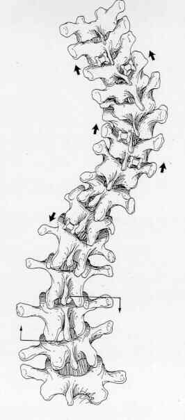
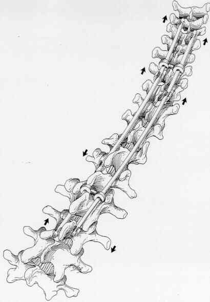
Technique Overview: The strategy for instrumenting a King-Moe Type I or II curve (Figure 19) is similar to that used for a Type III curve. The primary difference is that the lumbar curve is fractionally instrumented with use of a down-going hook at L1 on the convex lumbar, concave thoracic side and an up-going hook on the same side one level below the apex of the lumbar curve. This portion of the construct 46 clamps" a convex portion of the lumbar curve, thereby helping to preserve lumbar lordosis in the clamped segment. The L1 down-going hook is one of the Harrington-style lumbar hooks, and the up-going end hook is a lumbar up-going hook. The down-going lumbar hook serves as the base for a construct similar to that used for a Type III curve on the concave thoracic side. Because the clamp" protects against lower hook dislodgment, no end wire is needed. On the lumbar concave, thoracic convex side, a down-going lumbar laminar hook will be used at the same lamina chosen for the lumbar end up-going hook on the opposite side. Thus, there will be two hooks on this vertebral lamina. The next more cephalad hook on this side should be one level below the apical vertebra of the thoracic curve, and the most cephalad hook should be positioned using the same upper hook placement criteria as used for a Type III curve. While the correction sequence may be tailored to the particular deformity, the usual most effective sequence is to: 1) place all hooks except the lumbar end hooks, 2) lock up a down-going lumbar laminar hook onto the lumbar concave, thoracic convex rod and contour the rod for desired lumbar lordosis and thoracic kyphosis, place two locking sleeves on this rod and cut it to length, 3) place the end lumbar hook onto the end vertebral lamina and position the rod to pass through the subapical hook, slide the central lock up sleeve into a partially locked position, 4) mount the OCSTM instrumentation on the lumbar concave end hook and the subapical hook on the same side, apply firm distraction and lock up the subapical hook, remove the OCSTM instrument, 5) lock up an up-going lumbar end hook onto the end of the lumbar convex, thoracic concave rod and contour the rod for lumbar lordosis and thoracic kyphosis, add the three needed locking sleeves and trim the rod to length, 6) secure the up-going lumbar laminar hook on the end vertebral lamina and position the rod to pass through the down-going L1 laminar hook, slide the locking sleeve into a partially locked position, 7) using inboard tools, apply light compression force across the clamp constrict and lock up the LI hook, and 8) complete the remainder of the instrumentation as was done for the Type III curve (Figure 20).  The goals are not clearly defined in terms of selecting the end lumbar vertebra when instrumenting a Type I or Type II curve. It is uncertain whether to make the open lumbar motion segments horizontal. Even with obliquity of the lumbosacral motion segments, Harrington believed instrumentation should never extended to L5 or below. Theoretically, all open motion segments should be horizontal, but segment anterior release, perhaps with instrumentation, may not be justifiable. However, an anterior release in longer, structural lumbar deformities yields the best radiographic appearance. In instrumenting a flexible lumbar curve than 45 degrees, an L1 to L2 or an L1 clamp strategy is recommended with adjustments for the end lumbar vertebra and the flexibility of the curve. The problem of truncal decompensation seen with selective thoracic instrumentations has not been encountered.
 The goals are not clearly defined in terms of selecting the end lumbar vertebra when instrumenting a Type I or Type II curve. It is uncertain whether to make the open lumbar motion segments horizontal. Even with obliquity of the lumbosacral motion segments, Harrington believed instrumentation should never extended to L5 or below. Theoretically, all open motion segments should be horizontal, but segment anterior release, perhaps with instrumentation, may not be justifiable. However, an anterior release in longer, structural lumbar deformities yields the best radiographic appearance. In instrumenting a flexible lumbar curve than 45 degrees, an L1 to L2 or an L1 clamp strategy is recommended with adjustments for the end lumbar vertebra and the flexibility of the curve. The problem of truncal decompensation seen with selective thoracic instrumentations has not been encountered.
 Original Text by Clifford R. Wheeless, III, MD.