

1) Because WRIGHTLOCK rods have a smaller diameter than other systems, the rods will seem flexible. However, a fully assembled WRIGHTLOCK construct will create rigidity comparable to a large rod system. The OCS instrumentation helps ensure a maximum correction by allowing the surgeon to plan the strains in the rods. With a large rod system, the surgeon plans the forces to be applied to the spine. 2) The lowest possible implant profile is recommended for the outboard distraction technique. Usually, this means using 4 mm bifid hooks, 6 mm or 8 mm thin-shoed laminar hooks, and fixed or small adjustable couplers. These components will usually allow the rods to be placed against the spine. If a derotation technique is to be used, these components may not provide sufficient clearance. 3) In a patient with some thoracic kyphosis, the distraction hook holders may be tilted apart such that a single distraction hook holders be in a right angle relationship to it. In this case, the long and short distraction racks can be used together, joined by a 20 degree, 30 degree, or 40 degree rack connector. The distraction unit is then used as if it were a single angled rack. 4) The WRIGHTLOCK Spinal Fixation System was designed not only to provide secure, rigid fixation, but also with an inherent positive corrective force in the implant/sleeve assembly. Because the hook body automatically moves forward 2-3 mm during final seating, additional distraction steps may be eliminated. This inherent corrective force may result in decreased operative times once the surgeon is familar with the system. 5) The surgeon may determine the amount of correction obtained during full lock-up by understanding that the hook will move over the sleeve and assume the sleeve's position on the rod. Prior to final locking of any sleeve, the surgeon should ensure that there is sufficient anatomical laxity force. (Figures: 18a, 18b, 18c, 18d)
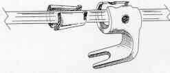
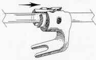 Figure 18a Figure 18b
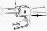
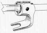 Figure 18c Figure 18d