
Rajasekaran, S. Dilip Chand Raja, and Ajoy Prasad Shetty
INTRODUCTION
Pedicle screws with its capability to achieve three-column fixations and higher fusion rates have revolutionized the use of instrumentation in spine surgery. They provide good biomechanical anchorage by achieving three-column fixations and, therefore,permits the surgeon to avoid long segment fixations.Theyare now used in a wide array of clinical conditions,which include trauma, tumors, infections, deformities and degenerative diseases. Pedicle screw placement by freehand techniques is primarily based on anatomical landmarks, and various methods have been described so far based on cadaveric studies. The high variability in the morphology of pedicles makes it more challenging in complex spinal deformities. Fluoroscopy can assist screw placement; however, it increases the operative time and radiation exposure to the surgeon and theater personnel. Misplacement rates of upto 30% in the lumbar spine and upto 50% in the thoracic spine have been reported with freehand and fluoroscopic guided pedicle screw placement. Malpositioned screws risk potential damage to the spinal cord, nerve roots and great vessels; and also decrease the stability of the fixation. Medicolegal concerns over patient safety have further reinforced the need for image-guided screw placements to improve accuracy.
Computer-assisted spine surgery (CASS) is a discipline that uses novel computer-based technologies, including stereotaxy, navigated surgery and robotics. Navigation assisted spine surgery is a group of technologies, which allow the surgeon to access real-time, three dimensional and virtual images of the spine in relation to the surgical instruments intraoperatively.1 This is a combination of image acquisition and processing that is followed by intraoperative navigation.The primary goal of navigationis to optimize the surgical interventionbyproviding the surgeon with advanced visualization of the operative field and to see the exact position of the handheld instrument in relation to the bony anatomy. The overall benefits include accurate and safe instrumentation, minimal radiation exposure to the surgical team, reduction of surgeon fatigue and surgical duration. Spine navigation was initially used to improve the accuracy of pedicle screw placement. However, over the years, its use has extended into minimally invasive surgical techniques, cervical spine surgery, revision surgery and spine tumor surgery.2
COMPONENTS IN SPINE NAVIGATION SYSTEMS
There are numerous navigation systems available commercially now. The basic fundamentals, however, remain the same and include the following.
Image Acquisition and Processing Unit
The first step in spinal navigation is to acquire high-resolution images of the region of interest,either preoperatively or intraoperatively, which then allows the surgeon to navigate upon these processed images.The acquisition of images in preoperative imaging was in the supine position, and the patient was turned over to a prone position during the surgical procedure. As a result of intersegmental mobility, there was a need for the manual intraoperative registration process, which was at times cumbersome and inaccurate. Intraoperative imaging is currently being used in most navigated surgeries as it involves the acquisition of images after positioning the patient for surgical intervention, and this reduces the rate of errors in matching and registration. Intraoperative imaging can be done either by fluoroscopy, computerized tomography (CT) scan and of late even magnetic resonance imaging (MRI).3
ReferencingSystem
This includes Dynamic Reference Frame/Array (DRA), Light Emitting Diodes (LED) and Tracking system.
Dynamic reference array
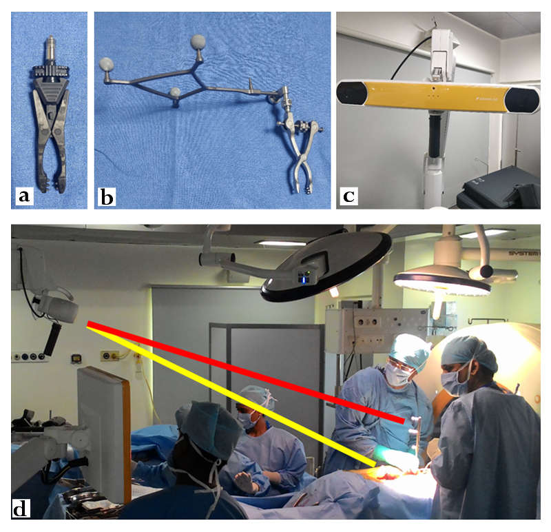
The dynamic reference array (DRA) is usually attached to fixed anatomical landmarks, such as the spinous process. The preoperative image is taken along with the fixed DRA(Fig.14-1a), which serves to synchronize between the virtual navigated images and anatomical landmarks.4 The accuracy of the navigation depends on the stable fixation of this DRA, and, therefore, it must be left undisturbed throughout the surgery. When there is no adequate fixation point within the surgical field as in revision surgery, hypoplastic or immature bone, the iliac crest can be used by inserting a pin into it. In cervical spine surgery, where the distance from the iliac crest is more, the reference array could be fixed to the Mayfield frame.
Light-emitting diodes
DRA has provisions for attaching three or more spheres known as light-emitting diodes (LED). These LEDs (Fig.14-1b) emit light, which is tracked by anelectro-optical camera and are known as active arrays. Specialized surgical instruments are used, which also have LEDs attached to them and are called passive arrays as they reflect the infrared rays emitted from the camera and gives the surgeon a real-time tracking of the exact location of these devices over the surgical field. The 3D orientation between these active and passive LEDs, thus facilitates navigation.
Tracking system
Various tracking systems are available that includeoptical, mechanical, acoustic or electromagnetic systems. Optical tracking systems (Fig. 14-1c) are the most frequently used due to superiority in terms of accuracy. They use infrared camera devicesto actively track the light emitted or reflected from the LEDs, which are attached to the DRA and surgical instruments. They calculate the location and provide real-time three dimensional positional data of the handheld surgical instruments in relation to the surgical field. This requires the “line of sight” maintenance between the LEDs and cameras at all times (Fig. 14-1d). Hand movements or excess operating personnel across this line of sight might hinder the navigation process. Electromagnetic systems allow an unobstructed view between transmitter and receiver. However, significant interference of the images can occur due to metal artifacts and electromagnetic fields originating from other commonly used operating room devices such as cautery and electrocardiogram monitoring equipment.
Registration Process
The process of establishing the synchronization between virtual images and the real anatomy is called registration and is of three types.5 (1) Paired point registrationrequires the surgeon to manually match the known anatomical landmarks with the virtual images, increasing the number of points,which ensures better accuracy. (2) With surface matching, the pointer is placed on a single point on the bone surface, and an auto-correcting algorithm matches this point with a preoperative image within seconds. (3) Automatic registrationdoesn’t require the placement of the navigation pointer on an anatomic surface.This technique involves attachment of DRA on the exposed spine and a second reference frame on the flouro or the CT scanner. Once the image is acquired, the data is transferred to the navigational system, which then performs an automated registration eliminating the need for manual registration. Of late, soft tissue details can also be added to the bone map using CT-MRI coregistration, which has immense benefits in tumor surgery.
| Image acquisition | 2D fluoroscopy | 3D fluoroscopy | Preoperative CT | Cone Beam CT | Intraoperative CT |
| Registration | Automated | Automated | Manual and time consuming | Automated | Automated |
| Registration duration | Short | Short | Long | Short | Ultra-Short |
| Image display | 2D (AP and Lateral) | 3D | 3D | 3D | 3D |
| Scan time | Only AP and lateral radiographic images | 2minutes | 30 seconds | 40 seconds | 30 seconds |
| Number of vertebrae in single scan | 3-5 vertebrae | 3-5 vertebrae (working corridor 12x12 cm) | Whole spine | 6-8 vertebrae (working corridor 30x40 cm) | Whole spine |
| Bone image quality | Poor | Poor | Good | Good | Good |
| Imaging in severe deformities | Not possible | Not possible | Possible | Possible | Possible |
| Carbon table and carbon head clamp fixation | Not necessary | Required | Not necessary | Required | Required |
| Ideal area of the spine | Lumbar spine | Whole spine | Whole spine | Whole spine | Whole spine |
| Minimally invasive spine surgery | Difficult | Possible | Not possible | Possible | Possible |
| Real time imaging | Yes | Yes | No | Yes | Yes |
| Radiation Exposure | Patient↓
OT Personnel↓ |
Patient↓
OT Personnel↓ |
Patient↑↑
OT Personnel↓ |
Patient↑
OT Personnel↓ |
Patient↑↑
OT Personnel↓ |
GENERATIONS OF NAVIGATION SYSTEM
The history of spine navigation systems can be considered to have undergone three generations of evolution.The current day navigation systems have their roots in the stereotactic brain surgery used in neurosurgery.6 The reference frame used in stereotactic brain surgery forms the basis of existing reference arrays, which are used for a spine navigation system.
First Generation Spine Navigation
First-generation spine navigation systems employed image acquisition using thin-slice CT scan preoperatively. The calibration of the reference array on the preoperative CT scan is performed by manual point-matching of anatomical landmarks intraoperatively. This registration process was long and tedious and often required multiple registrations during the surgical process, thus prolonging the duration of surgery. In addition, due to the intersegmental mobility and difference of positioning between real and virtual images, it resulted in inaccuracies. There are two modes of instrumenting either in “guidance mode” where the trajectories are planned preoperatively, and the exact entry point is shown or in “real-time mode” where the navigated instruments as they are moved can be seen in reference to a matched vertebra.7
Second Generation Spine Navigation
Second generation spine navigationmanaged to overcome the shortcomings noted in the first generation. They offered intraoperative reconstruction images of the spinal anatomy using two-dimensional (2D) and three-dimensional (3D) fluoroscopy. The 2D fluoroscopy system provided images in two planes. Axial reformatting was not available, limiting the clinical utility in complex spine surgery. The image quality in this system was dependent on other factors such as the presence of osteoporosis and obesity, which often resulted in distorted images unfit for navigated surgery. The advantage of this system was thatthe computer software and image acquisition system could be paired with routinely used fluoroscopy units available in the operating room.8
Further improvement was seen in the form of cone-beam CT that used basic multiplane fluoroscopy to reconstruct three-dimensional CT like images. The drawbacks were that limited segments of the spine could only be scanned during the process. This made multiple level fixation spanning long segments difficult as multiple scans needed to be performed for a single procedure, increasing the radiation exposure, and operative time.
3D C-ArmNavigation System
This system depends on the concept of isocentricity. The fluoroscopy unit is coupled with a special reference system and computer software to provide axial, sagittal and coronal reformatted images. The fluoroscopy unit moves through an arc of 180º while focusing on a solitary point in the spine. The system can be calibrated to a high spatial resolution protocol, which takes multiple fluoroscopy images while the arc moves through the 180º or lower resolution protocol, which may take fewer images during the process. The system allows for automatic reference. The advantage of the system was that it did not require a preoperative CT scan.Intraoperative image acquisition allowed for a postoperative scan to assess the accuracy of the screw position possible. The 3D C-Arm can be used as a routine fluoroscopy unit and can be paired with image guidance surgery software to work as a navigation system for complex spinal surgery.9
However, there are a few disadvantages to this navigation system. It scans patients based on the selected isocenteric point. Therefore, all the images obtained are from a segment of the spine in the field of the scan. This limits the scan to 6-7 vertebral segments. In scoliosis, where the instrumented level can extend to 10-12 segments, a repeat scan to view the entire region of interest is needed. The additional scan increased the operative time, and the cumulative radiation dose received by the patient.Moreover, in complex kyphoscoliotic deformities,isocentricity cannot be achieved & this results in inadequate & poor 3D reformation of the images of the region of interest.Although the images generated by the 3D C-Arm are similar to a reformatted CT scan, the image quality is inferior to conventional preoperatively performed CT scans. The images being generated from the fluoroscopy unit, limits the image quality, especially in obese and osteoporotic patients. This equipment could provide satisfactory images in procedures in a small region such as the cervical spine. But, the clinical utility was restricted in complex multi-segment spinal deformity correction procedures.
Cone Beam CT
Plenty of Cone Beam CT (CBCT) devices are available commercially, and again they can be used either preoperatively or intraoperatively. The image quality is superior to 3D C-Arm, and the time for image acquisition is also shorter. Intraoperative CBCT devices allow automatic registration and have a larger field of scan and, therefore, can screen more vertebral segments in a single scan when compared to the 3D-C Arm system. They can provide both routine fluoroscopy images and reformatted CT images in the axial, sagittal and coronal sections.10 The radiation dose of the CBCT devices, however, is lower than a conventional CT scanner, and it may be used to assess the accuracy of placement of screws intraoperatively.
Third Generation Spine Navigation Systems
Third generation spine navigation systemsare considered the most recent developments in the field. These navigation systems can perform an intraoperative CT scan with subsequent automatic registration. They provide excellent CT images with a scan field that can screen the entire spinal column.The advent of intraoperative CT scanners, combined with newer generation software systems, have given rise to total navigated spine surgery solutions.This system comes with the complete set of navigated instruments, including high-speed burrs, bone drills, taps, and navigated screw systems. It also offers an opportunity to use the navigation in conjunction with minimal access surgical procedure. The radiation exposure to the patient with the use of such CT based systems can be much higher than fluoroscopy-based navigation systems.11 These imaging devices have adjustable radiation density thresholds, which provide good images even when the density is reduced by 25-50% of the maximum dosage.
Basics of Pedicle Screw Insertion Using Navigation
After positioning the patient, the surgical exposure is done in a standard manner, and the DRA is attached to the spinous process usually (Fig. 14-2a). Stable fixation of the DRA is ensured before proceeding to intraoperative image acquisition and processing. Following image acquisition, automatic registration of images takes place. Then the accuracy of navigation is checked by positioning the navigation probe/pointer over known anatomical landmarks such as spinous process, transverse process and lamina. The verification of probe location in the virtual images displayed in the workstation as compared to the surface anatomy is performed (Fig. 14-2b). Further, live tracking of the probe can be done by running down the pointer on the outer surface of lamina. The mismatch between the real and virtual positions indicates an error in the registration process and warrants re-registration (Fig. 14-2c).When the navigation pointer is placed perpendicular to the longitudinal axis of the spine, the imaging workstation displays images in sagittal, coronal and axial planes. Reformatted images visualized by the surgeon, change according to the inclination and direction of the probe, thus allowing the surgeon to perceive the three-dimensional spinal anatomy, which is not visible to naked human eyes. Both calibrated and non-calibrated surgical instruments are available. The appropriate entry point, angulation for the screw trajectory is determined by placing the probe appropriately. In addition, the screw dimension to be implanted is also determined by using superimposed images at the planned level. The next step may either be done with specially designed pre-calibrated surgical tools or with traditional screw insertion equipment. In the calibrated technique,all steps of pedicle screw instrumentation are doneunder navigation guidance with the special tools, which have passive arrays. If the non-calibrated technique is followed, the surgeon first notes the ideal entry point and then makes a mental note of the planned trajectory (Fig.14-2d,e,f). A pilot hole is then prepared with a burr (Fig. 14-2g) after which instrumentation proceeds in a standard freehand manner with periodic checks of the trajectory being created using the navigation probe. Powered surgical equipments (Fig.14-2h) are preferable in order to avoid wobbling and motion-related artifactsin this scenario. An appropriately sized screw is finally inserted into the created trajectory (Fig 14-2i).

ADVANTAGES OF NAVIGATION ASSISTED SURGERY
Accuracy
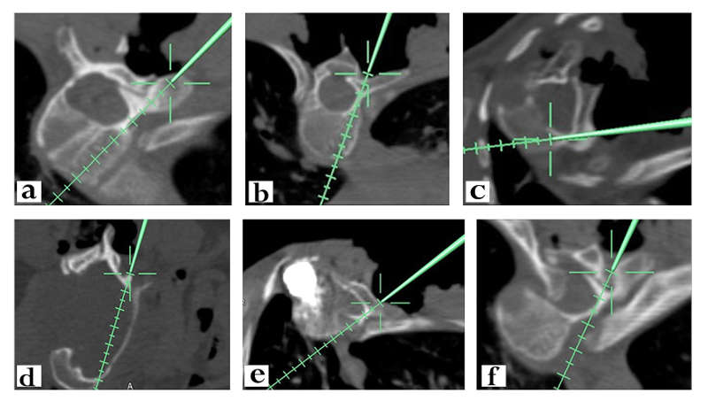
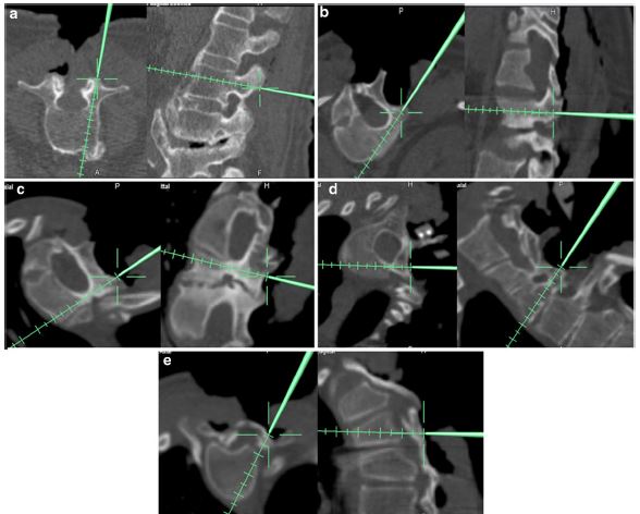
The demand for accuracy of instrumentation in navigation surgery is determined by various factors, which include surgical expertise, surgical approach (posterior or anterior), level of instrumentation (cervical/thoracolumbar/lumbosacral), presence of deformity and the morphology of the pedicles under consideration. Navigation assisted screw positioning has reported lower misplacement rate compared to the freehand placement. The variability in accuracy rates reported by different authors is because of the comparisons done amongst different groups of patients. The efficacy of navigated surgery should not be compared with freehand techniques in routine elective surgeries where the pedicles are relatively less dysmorphic. The real benefit of navigation comes to cases of trauma, revision surgeries and congenital deformities, and neurofibromatosis where the pedicles are small, disparate, dysmorphic and are variably angulated (Fig.14-3). In addition, it has been found to be beneficial to identify the zones of spinal canal requiring adequate decompression and has been able to localize the intra canalicular rib heads as seen in neurofibromatosis for excision (Fig.14-3f). Rajasekaran et al. in a recent article have analysed pedicles based on its intraoperative appearance using navigation and classifiedinto five types according to the complexity of screw insertion. Type 1 is normal anatomy, primary surgery and no deformity; type 2—deformity surgery and revision lumbar surgery; type 3—revision cervical and thoracic surgery,altered pedicle anatomy, and congenital deformity; type4—pedicle screw insertion unsafe without navigation due to complex trajectory; and type 5—pedicle unfit for screwinsertion(Fig. 14-4).12 In this study, they documented an accuracy rate of 96.2% using intraoperative CT based navigation. In addition to pedicle screw placement, navigation helps to classify these non-negotiable pedicles and prevents the surgeon from attempting to instrument it. Free hand technique attempted at such pedicles would invariably enter the spinal canal causing neurological complications, or it might slip anteriorly and cause pulmonary and vascular complications. The superiority of navigation has been reported in cervical surgery by Acosta et al. with a misplacement rate of 8% compared to 22% with conventional techniques.13Rajasekaran et al. documented an accuracy rate of 89.7% using 3D fluoroscopy navigation-assisted cervical pedicle screws in complex deformities.14 Liu et al.in his comparison between conventional C-Arm, 3D C-Arm and CT guided navigation for cervical pedicle screw instrumentation observed far superiority of 3D C-Arm and CT to conventional fluoroscopy in terms of screw placement.15 Free hand screw misplacement rates in thoracic spine is much higher than other spinal segments, and it becomes much more challenging in dysmorphic pedicles as seen in deformities and in areas where there is distortion of normal anatomical landmarks such as trauma, revision surgeries and ankylosed spine. Navigation has resulted in pedicle perforation rates as low as 1–5%. The accuracy of 3D navigation system is considered to be superior to virtual fluoroscopy and 2D navigation.16A meta-analysis of 9019 thoracic pedicle screws established the superiority of CT navigated instrumentation over fluoroscopic guidance.17 Though the overall accuracy of navigated surgery is far more promising and superior to freehand technique, Thorsten Tjardes said there is always a possibility of error due to the human factor (the surgeon) involved in the procedure.18
Operative Time
The older generation of navigation systems employing manual point matching registration did lead to increased operative times. The smaller field of scan, limited procedures involving multiple level fixation and resulted in the need for multiple scans for a single procedure. This drawback has been overcome with newer generation navigation systems that allow for automatic registration and a larger field of scan extending to multiple vertebral segments. As with any new technology, a substantial learning curve is associated with the use of navigation in spine surgery. This is illustrated by the wide range in screw insertion times reported by different authors. The technical complexity of the surgery and a difficult screw trajectory, especially in the deformed spine, can have an independent bearing on the screw insertion time. Shin et al. have shown that the meantime for the insertion of a pedicle screw was 3.79 minutes in the fluoroscopy-guided group and 4.45 minutes in O-arm navigation guided group.19 Conversely, Rajasekaran et al. reported a significantly shorter time required to insert a pedicle screw using 3D C-Arm in Scoliosis. In their study, the average screw insertion time in the non-navigation group has 4.61 + 1.05 minutes compared to 2.37 + 0.72 minutes in the navigation group.20 Similar decrease in operating time while using image-guided navigation has been recorded by multiple authors.21 However, a meta-analysis showed no difference in the operating time between navigated and non-navigated pedicle screw.22 Improvement in quality of virtual images, reduction in acquisition time, and automatic registration process has contributed to the reduction in the duration of a surgery over the years. The overall duration is set to improve steadily as the experience of the surgeon and operating room personnel rises resulting in a systematic workflow in the long run.
Radiation Safety
The radiation exposure in navigation surgery depends on the scan duration, nature of navigation system (fluoroscopy based versus CT-based), number of levels and number of scans needed to complete procedure. Radiation exposure in navigation surgery has to be considered separately in context to the patient and for the operating team as there is a substantial difference in the radiation exposure for these groups. It has been noted that for the spine surgeons, radiation exposures is up to 10–12 times greater than in other Orthopaedic procedures and may approach or exceed guidelines for cumulative exposure.23 The radiation exposure is much higher in minimally invasive spine surgery (MISS) and percutaneous procedures. Routine fluoroscopy when used in complex spine surgery can increase the radiation dose to the surgeon, nursing staff and other theater personnel. In such a scenario, navigation-assisted surgery reduces the radiation exposure for the operative team, as all members are protected during the scanning procedure. Mendelsohn et al.reported that radiation exposure to patients using O arm navigation was 2.77 times more when compared to non-navigated surgeries. However, the dose of 5.69 mSv was much lower than a conventional CT (7.5 mSv) and amounts to one-quarter of the total occupational exposure allowed per year. They also found 87% less exposure time to radiation while using intraoperative CT in comparison to fluoroscopy used in MIS procedures.24From the patient’s perspective, the radiation exposure for CT based navigation systems is significantly higher when compared to fluoroscopy-based systems, yet they fall within permissible limits.
CONCERNS WITH SPINE NAVIGATION
In spite of the precision and accuracy of these navigation platforms, there are certain concerns regarding navigated surgery that include motion-related artifacts, cost-effectiveness and learning curve.
Wobbling and Motion Related Artefacts
Whilst the entry points and trajectories of instrumentation are clearly defined by image-guided surgery, the wobble created by manually tapping or inserting screws across the trajectories involved might result in inaccuracies due to the maximal radial movement from its center of axis.25 This is best avoided by postponing the screw insertion process after creating trajectories of all planned screws. Nowadays, powered pedicle screw drive systems are available which enhance surgeon experience with faster, accurate screw insertions. In lean and poorly built patients, ventilation related movement of the thoracic spine may hinder the accuracy of navigation. It is better to acquire images in a non-ventilation mode and reduce the tidal volume in such scenarios to reduce motion-related artifacts. More important, all the nursing staff and assisting surgeons who are involved in the handling of instruments around the surgical field must be aware of the fact that the slightest deflection of the fixed reference array might result in severe inaccuracy. In doubtful scenarios, the surgeon needs to re-verify the accuracy. If the tip of the pointer appears to be either underneath the lamina or hanging above in space, one can be sure that there has been a disturbance of the array, and the entire navigation needs to be repeated (Fig.14-2c). Some times in spite of placing the surgical instruments and camera in the “line of sight,” navigation might be troublesome. It might be due to bloodstain or debris covering the spherical diodes. Care should be taken to gently clear it to avoid disturbing the position of reference array.
Distance from Reference Array
The accuracy of instrumentation is directly proportional to the distance of the level of interest from the reference array. Even though the current systems are capable of imaging the whole spine, the accuracy is questionable at the farthest point from the reference array. This can be solved in two ways. Firstly, when the surgeon requires imaging of the entire spine in case of complex deformity and surgery involves more than 12 segments, it would be appropriate to affix the reference array midway between the ends of the surgical incision. On the other hand, where the surgeon is not able to get an adequate fixation point as in pediatriccervical spine, considering the far distance of iliac crest from the area of instrumentation, it would be better to place the reference array on immobile regions such as Mayfield clamp. Whenever instrumentation is attempted at distal levels, it is better to re-verify the accuracy manually.
Cost-effectiveness
The uptake of navigation technology has been limited by start-up, acquisition and maintenance costs. The opponents of spinal navigation cite this as one of the major drawbacks. The economical evaluations have recognized limitations and challenges as the cost-effectiveness depends on multiple factors such as the number of surgeries performed, the intricateness of surgical procedures undertaken, complications and the cost of revision surgeries. Medicolegal claims secondary to neurological deficits and revision surgeries are often not considered while assessing the cost-effectiveness of image-guided navigated spine surgery. Furthermore, the cost-effectiveness will vary across a spectrum ofcenterswith a high-volume academic training center at the top, and a low-volume single practitioner owned private center at the lowest possible end.Dea et al.performed an observational case-control analysis in cost-effectiveness of computer-aided navigation surgery.26 The major factor considered was the cost of revision procedure due to misplaced screws within one year of the index surgery. The econometric analysis revealed an incremental cost-effective analysis ratio of $15,961 for every revision surgery that could be avoided by navigated spine surgery.The study also concluded that it would actually bea cost-saving surgery for a spine unit that does more than 254 spinal instrumentations yearly.26Al-Kouja et al.in his systematic review states that the biggest advantage of image-guided surgery is the prevention of reoperation and four out of seven studies had a zero reoperation rate.27
Learning Curve
As with any new technology and its user experience, navigated spine surgery does have a learning curve. However, here, it requires well-organized operating room personnel to function as a single unit, and the success depends on the learning curve of the entire team. Predefining each one’s contribution and preparedness of the working staff is essential to ensure a smooth workflow. Each of the team needs to understand and execute their roles efficiently to reduce the nuances of surgical duration and technical flaws. The learning process involves three main steps: (1) the ability to achieve adequate imaging of spine without compromising the working space for instrumentation, especially in those requiring long segment fixations;(2) handling and directing instruments on surgical field based on images acquired;and (3) avoiding or most importantly recognizing errors during surgery. Bai et al.in his prospective study analyzed the learning curve of surgeons using image-guided navigation spinal surgery and noticed a steep incline in operating time and screw perforation rate by 6 months and reached a plateau by 12 months.28Sasso et al. in his retrospective analysis of 4-year data, noted an average reduction of 40 minutes in operative time for lumbar fusion using navigation and image-guided surgery.29 However, he couldn’t establish a plateau phase as throughout the duration of 4 years; there had been constant improvement. Ryang et al., in his prospective analysis of the learning curve using 3D fluoroscopy, found a learning curve of 4 months in placing lumbar and thoracic pedicle screws. He found a higher rate of inaccuracy in placing thoracic screws and a steep learning curve when compared to lumbar screws.30Thesurgeon’s ability to handle these instruments and perform surgical maneuvers has been linked to the modern generation of surgeons who have had exposure to video games. Rosser et al., in his cross-sectional analysis of residents and physicians attending the laparoscopic training program, observed faster and better performance in suturing and handling skills in those who had previous exposure to video games. He felt the need for integrating video and screen mediated applications in training sessions to improve the learning curve.31
| S.No | Factors | Resulting Errors | Solution |
| 1 | Poor fixation points for the dynamic reference array (DRA) | Deflection of DRA during procedure causing inaccuracy |
|
| 2 | Unrecognized deflection of DRA during surgical procedure | Mismatch between real and virtual images requiring re-registration |
|
| 3 | Wobbling of DRA during trajectory preparation | Inaccuracy of subsequent screws |
|
| 4 | Increase of tracking device distance from reference array | Mismatch between real and virtual images | Placement of DRA in-between upper and lower instrumentation levels |
| 5 | Blood or debris around diodes | Inability to navigate despite maintaining “line of sight” | Gently wipe out the blood stains and debris without deflecting DRA |
| 6 | Ventilation associated excursion of thoracic spine | Motion related artefacts | Acquisition of images either in non-mechanical ventilation mode or reduction in Tidal volume |
CLINICAL APPLICATIONS
The primary implication of adopting spinal navigation was to provide the surgeon with high resolution virtual three-dimensional topographic representation of the anatomical spine, which then allows the surgeon to perform accurate instrumentation, thereby reducing the complications associated with misplaced screws. Spine surgeries are intricate procedures that may be long and arduous at times, imparting both mental and physical fatigue to the surgeon. This intraoperative stress might contribute to errors in judgment and decision making and, henceforth, be detrimental in terms of surgical outcomes as reported by Wetzel et al.32 Spinal navigation improves the surgeons’ manual dexterity by providing greater control and maneuverability, while dampening the concern on surgical experience, especially in complex procedures.
Constant improvement in these navigation platforms over the past four decades has witnessed the expansion of their clinical applications from pedicle screw placements to surgical excision of tumours, revision procedures, minimal invasive procedures and deformity correction. This progress has been mainly due to the integration of high quality Intraoperative MRI and CT images with navigation technology. The availability of various precalibrated tools which are ready to use for navigated surgery such as pedicle awls, probes, drill bits, osteotomes and k-wire drill guide, further enhance the navigated surgical experience.
Cervical Spine
Traditional instrumentation of cervical spine using inter-laminar wiring saw a revolutionary change when Roy-Camille used lateral mass screws and later Abumi started using pedicles screws in trauma. However, instrumentation in cervical spine is still challenging due to its smaller anatomy when compared to thoracic and lumbar spine.33 Lateral mass screws have a lesser learning curve when compared to pedicle screw insertion, and malposition of lateral mass screws may violate facet joints and cause nerve root injury.34Arab et al.in his comparative analysis of lateral mass screw noted a 19.3% malposition rate in free hand technique much higher than the 11.1% rate observed using 3D navigation.35 Currently, pedicle screws are the most biomechanically strong equipment available. Shin et al.in his cadaveric study noted a high variability in shape and size of cervical pedicles not only between individuals but also between each level of the same individual and cautioned surgeons to be aware of this anatomic variability before instrumentation for safe surgical management.36 Moreover, the close proximity of critical neurovascular structures such as the vertebral artery and spinal cordmakes cervical instrumentation a daunting task for surgeons.The rates of pedicle screw misplacement under fluoroscopic guidance reported so far have varied from 6.7% to as high as 29.1%.Shimokawa et al.reported a lower misplacement rate of 2.9% using intraoperative CT based navigation surgery.37 Rajasekaran et al. evaluated the safety of 3D fluoroscopy based navigation in cervical pedicle screw insertion in thepediatric population and found to have only a non-critical breach of 11.7%.38 In another report, they had used a novel transverse rod technique to reduce a case of neglected C2-C3 dislocation under 3D fluoroscopy navigation.39 Added advantage is instrumentation in occipitocervical region where there are higher incidences of congenital anomalies of spine as well as anomalous vertebral arteries. Wakao et al. in his prospective analysis of 480 Japanese patients observed a 10% incidence of high riding vertebral artery.40 Navigation is useful to change the surgical strategy in a situation where a safe screw trajectory cannot be verified without injuring the vertebral artery. Jaiswal et al. evaluated the role of 3D C-Arm navigation assisted instrumentation in cervical trauma where the topographical landmarks may be altered due to fractures or at times not recognisable as in ankylosing spondylitis and revision surgeries and observed a pedicle breach rate of 6%. Direct transpedicular osteosynthesis of a Hangman fracture was possible, which on the other hand would have required C1-C2 fusion or occipitocervical fusion. Thus, they could avoid the morbidity of restricted range of movements.41 The benefits of navigation have also been demonstrated in anterior odontoid screw fixations and surgery in the cervicothoracic junctional region.42
Minimally Invasive Surgery
Minimally invasive spine surgeries (MISS) involve notoriously high amount of radiations to the surgeon and other operating room staff due to the non-visualization of anatomical landmarks for free hand placement of screws. Castro et al. noted a 40% pedicle breach following free hand pedicle screw placement in fluoroscopy assisted surgery in spite of anatomic visualization of entry points.43 MISS is likely to have much higher misplacement rates. Navigated spine surgery has the potential to create phantom screw trajectories and helps the surgeon to apply stab incision at the appropriate level through which screws can be placed with ease in correlation with these phantom images. Baaj et al. used intraoperative navigation to apply percutaneous pedicle screws in short constructs in degenerative spine.44 Kim et al. observed an accuracy rate of 96.6% in MISS using computer aided navigation and intraoperative CT.45 There is also a high chance of facet joint violation in MISS which in turn results in adjacent segment degeneration. Lau et al. observed lesser facet joint violations in MISS while using intraoperative navigation.46 Instrumentation using MISS in obese patients and frail osteoporotic patients is challenging as manual tactile feel of the pedicles would not be possible, and spinal navigation comes to the rescue in such scenarios.
Spine Deformity
The role of navigated spine surgery in deformity has been fiercely debated, and there are equal number of reports for and against its use. Suk et al. popularized deformity correction by using pedicle screws, and since then the pedicle screw continues to be the workhorse of deformity correction as it fixes three columns and, henceforth, allows effective derotation and achieves a three-dimensional correction.47 It is a well-known fact that the strength of fixation and amount of deformity correction increases proportionately to the number of anchor points. Liljenquist etal. noted that morphometry of pedicles at the apex is highly varied and precludes safe placement of screws especially on the concave side where there is a spinal cord shift resulting in a limited epidural safe zone.48 Hicks et al.in his systematic review noted that thoracic screw misplacement was the commonest complication in scoliosis surgery.49 Tian et al. in his recent meta-analysis showed that navigation assisted deformity correction achieved significantly lesser screw misplacement and had no additional operation time or impact on deformity correction. More importantly, the average screw insertion time was much shorter than free hand technique, and he suggested repeated usage of navigation, which would constantly improve the proficiency of the team and would cut down the preoperative and registration time to reduce the overall surgical duration.50 Furthermore, Zhang et al. in his comparative study of preoperative and intraoperative CT-assisted navigated surgery observed that intraoperative CT allows better and safe placement of pedicle screws in the apex especially on the concave side which according to Suk et al. allows better derotation, deformity correction and reduces the chance of pedicle breakage and implant failure.47,51
In addition a real time three dimensional view of the apex of deformity helps the surgeon to plan an osteotomy in order to achieve better deformity correction and restore balance in all three planes.
Spinal Tumours
The key to successful outcome in musculosketal malignancy is to obtain a clear margin of resection. Navigated surgery gives a three-dimensional real-time imaging of the area of interest and defines the extent of tumour, which allows adequate removal. In addition, a malignant lesion may often encase or displace neurovascular structures and might result in inadvertent damage to these vital structures.A typical case of cervical lateral osteoid osteoma where navigation was useful to perform a minimally invasive surgery is illustrated in Figure14-5. Navigation allows identification of anatomical landmarks covered by the tumours such as foramen transversarium, which encloses the vertebral artery and helps the surgeon in becoming more cautious while removing these lesions involving lateral masses of cervical spine (Fig.14-5f). Stefini et al. used combined intraoperative fluoroscopic images and preoperative MRI images to perform navigated intradural tumour surgeries.52 Some of the claimed advantages include avoidance of wrong level surgery, minimal invasiveness and ability to determine the posterior midline sulcus to perform myelotomy in intramedullary tumours. Surgeons have had a high intralesional resection ratein pelvic and sacral tumours, leading to local recurrences ranging from 70-92%. Jeys et al. in his prospective analysis of malignant tumours of pelvis and sacrum observed a reduction of intralesional resection from 29% to 8.3% following use of computer navigation-assisted spine surgery. This reflected on local recurrence rate reduction from 27% to 13%.53 Rajasekaran et al. used navigation in intralesional excision of a cervical osteoblastoma in a minimally invasive approach and also in osteoid osteomas. In addition to the avoidance of neurovascular damage, they stressed the need of preserving normal bony structures, which might otherwise result in instability requiring fusion.54 Fujibayashi et al.described the use of 3D spinal osteotomy using computer navigated spine surgery to achieve en bloc resection of tumours.55 Nasser et al. in his multicentre analysis of 50 patients with spinal column tumours noticed and concluded that stereotactic navigation allowed better localization of lesions allowing adequate removal in a minimal invasive approach with lesser blood loss, surgical duration and complication rates.56

Complex Spino-pelvic Trauma
Sacral fixation with S1 and S2 screws do not cross the pivot point and may not provide adequate fixation across the lumbosacral junction, where there is a high chance of pseudoarthrosis and implant failure. Moreover, in sacral fractures and morphological variants, it would be impossible to place S1 and S2 screws. It is a well-known fact that iliac, S2 alar iliac and sacroiliac (SI) screws are the best available points of fixation and provide robust construct across the lumbosacral junction, especially in lumbopelvic trauma. However, the complex anatomy and narrow osseous corridors pose a great challenge to the surgeon. Moreover, safe placement of screws requires extensive soft tissue dissection and repeated fluoroscopic checks during screw insertion. Navigated spine surgery allows percutaneous placement of screws with good accuracy since it provides a three-dimensional orientation. Garrido et al., in his case series, described the navigated placement of traditional and anatomical iliac screws with ease, lesser blood loss and was able to avoid excess soft tissue dissection.57 Thakkar et al. in a review article on the percutaneous placement of SI screws in closed posterior pelvic ring fixation using 3D fluoroscopic navigation found it to be associated with lesser radiation exposure and lower screw malposition rates when compared to conventional 2 D fluoroscopy.58 Ray et al.observed the usefulness of navigation on placing S2 alar iliac screws and felt that it enhanced the surgical performance in choosing the right trajectory and ensured a screw of adequate length.59
CONCLUSION
The current navigation systems are user friendly and have high precision. Apart from the accuracy of instrumentation, navigation has additional benefits that include planning of effective osteotomy, ensuring adequate decompression, deformity correction, providing clear and safe surgical excision of tumours and enables better ergonomics in complex deformities. The surgeon’s ability to handle complex deformities and access critical zones of spine such as cervical and upper thoracic spine has been enhanced with navigation assisted surgery. The cost-effectiveness of navigated spinal surgery is ultimately rewarding, and as investment in high precision equipment that offers low radiation exposure and avoids revision surgery is an investment in quality health care. Navigation can always be used as an effective adjunct, but can never substitute clinical acumen, human practical skills and knowledge.
PEARLS AND PITFALLS
Pearls
- Spinal navigation improves the accuracy of spinal instrumentation, thereby reducing neurovascular complications and implant failures.
- Navigated surgery reduces surgical duration and radiation exposure to the operating room personnel.
- It allows intraoperative assessment of tumour margins, which helps the surgeon to obtain adequate surgical resection of tumours.
- In revision surgery and severe complex deformities, navigation allows the surgeon to instrument the pedicles with altered morphology and distorted anatomy.
- Intraoperative navigation is also useful to assess the accuracy of instrumentation and also adequacy of decompression following surgery.
Pitfalls
- Inadequate fixation points of the reference array such as in pediatric cervical spine, revision surgery and patients with immature hypoplastic bones requires alternate stablefixation options such as iliac crest or Mayfield Clamp.
- Unintended or unnoticed displacement of reference array would result in inaccurate pedicle screw placements.
- In cases of long segment instrumentations, the accuracy decreases as the distance of navigation probe from the reference array increases, and this can be prevented by placing the DRA in between the ends of fixation.
- Though CT navigation surgery results in an acceptable level of radiation exposure to the patient, it is much higher than fluoroscopy assisted surgeries.
- The initial start-up and maintenance costs are high; however, in the long run, it is a cost saving equipment especially for a high volume spine surgical unit.
REFERENCES
- Nolte LP, Visarius H, Arm E, Langlotz F, Schwarzenbach O, Zamorano L. Computer-aided fixation of spinal implants. J Image Guid Surg. 1995;1(2):88-93.
- Overley SC, Cho SK, Mehta AI, Arnold PM. Navigation and robotics in spinal surgery: where are we now? Neurosurgery. 2017;80(3S):S86-S99.
- Helm PA, Teichman R, Hartmann SL, Simon D. Spinal navigation and imaging: history, trends, and future. IEEE Trans Med Imaging. 2015;34(8):1738-1746.
- O’Loughlin PF, Daentzer D, Hüfner T, Uksul N, Citak M, Haentjes J, et al. A customized modular reference array clamp for navigated spine surgery. Arch Orthop Trauma Surg. 2010;130(12):1475-1480.
- Mezger U, Jendrewski C, Bartels M. Navigation in surgery.Langenbecks Arch Surg. 2013;398(4):501-514.
- Drazin D, Kim TT, Polly DW, Johnson JP. Introduction: Intraoperative spinal imaging and navigation.Neurosurg Focus. 2014;36(3):Introduction.
- Schlenzka D, Laine T, Lund T. Computer-assisted spine surgery. Eur Spine J. 2000;9 Suppl 1:S57-64.
- Du JP, Fan Y, Wu QN, Wang DH, Zhang J, Hao DJ. Accuracy of pedicle screw insertion among 3 image-guided navigation systems: systematic review and meta-analysis. World Neurosurg. 2018;109:24-30.
- von Recum J, Wendl K, Vock B, Grützner PA, Franke J. [Intraoperative 3D C-arm imaging. State of the art].Unfallchirurg. 2012;115(3):196-201.
- Epstein NE. Commentary: Utility of the O-Arm in spinal surgery. Surg Neurol Int. 2014;5(Suppl 15):S517-S519.
- Barsa P, Frőhlich R, Šercl M, Buchvald P, Suchomel P. The intraoperative portable CT scanner-based spinal navigation: a viable option for instrumentation in the region of cervico-thoracic junction. Eur Spine J. 2016;25(6):1643-1650.
- Rajasekaran S, Bhushan M, Aiyer S, Kanna R, Shetty AP. Accuracy of pedicle screw insertion by AIRO® intraoperative CT in complex spinal deformity assessed by a new classification based on technical complexity of screw insertion. Eur Spine. 2018;27(9):2339-2347.
- Acosta FL Jr, Quinones-Hinojosa A, Gadkary CA, Schmidt MH, Chin CT, Ames CP, et al. Frameless stereotactic image-guided C1-C2 transarticular screw fixation for atlantoaxial instability: review of 20 patients. J Spinal Disord Tech. 2005;18(5):385-391.
- Rajasekaran S, Kanna PR, Shetty TA. Intra-operative computer navigation guided cervical pedicle screw insertion in thirty-three complex cervical spine deformities. J Craniovertebr Junction Spine. 2010;1(1):38-43.
- Liu YJ, Tian W, Liu B, Li Q, Hu L, Li ZY, et al. Comparison of the clinical accuracy of cervical (C2-C7) pedicle screw insertion assisted by fluoroscopy, computed tomography-based navigation, and intraoperative three-dimensional C-arm navigation. Chin Med J (Engl). 2010;123(21):2995-2998.
- Silbermann J, Riese F, Allam Y, Reichert T, Koeppert H, Gutberlet M. Computer tomography assessment of pedicle screw placement in lumbar and sacral spine: comparison between free-hand and O-arm based navigation techniques. Eur Spine J. 2011;20(6):875-881.
- Meng XT, Guan XF, Zhang HL, He SS. Computer navigation versus fluoroscopy-guided navigation for thoracic pedicle screw placement: a meta-analysis.Neurosurg Rev. 2016;39(3):385-391.
- Tjardes T, Shafizadeh S, Rixen D, Paffrath T, Bouillon B, Steinhausen ES, Baethis H. Image-guided spine surgery: state of the art and future directions. Eur Spine J. 2010;19(1):25-45.
- Shin MH, Ryu KS, Park CK. Accuracy and safety in pedicle screw placement in the thoracic and lumbar spines: comparison study between conventional C-Arm fluoroscopy and navigation coupled with O-Arm® guided methods. J Korean Neurosurg Soc. 2012;52(3):204-209.
- Rajasekaran S, Vidyadhara S, Ramesh P, Shetty AP. Randomized clinical study to compare the accuracy of navigated and non-navigated thoracic pedicle screws in deformity correction surgeries. Spine. 2007;32(2):E56-64.
- Dusad T, Kundnani V, Dutta S, Patel A, Mehta G, Singh M. Comparative prospective study reporting intraoperative parameters, pedicle screw perforation, and radiation exposure in navigation-guided versus non-navigated fluoroscopy-assisted minimal invasive transforaminal lumbar interbody fusion. Asian Spine J. 2018;12(2):309-316.
- Shin BJ, James AR, Njoku IU, Härtl R. Pedicle screw navigation: a systematic review and meta-analysis of perforation risk for computer-navigated versus freehand insertion. J Neurosurg Spine. 2012;17(2):113-122.
- Rampersaud YR, Foley KT, Shen AC, Williams S, Solomito M. Radiation exposure to the spine surgeon during fluoroscopically assisted pedicle screw insertion. Spine. 2000;25(20):2637-2645.
- Mendelsohn D, Strelzow J, Dea N, Ford NL, Batke J, Pennington A, et al. Patient and surgeon radiation exposure during spinal instrumentation using intraoperative computed tomography-based navigation. Spine J. 2016;16(3):343-354.
- Rahmathulla G, Nottmeier EW, Pirris SM, Deen HG, Pichelmann MA. Intraoperative image-guided spinal navigation: technical pitfalls and their avoidance.Neurosurg Focus. 2014;36(3):E3.
- Dea N, Fisher CG, Batke J, Strelzow J, Mendelsohn D, Paquette SJ, et al. Economic evaluation comparing intraoperative cone beam CT-based navigation and conventional fluoroscopy for the placement of spinal pedicle screws: a patient-level data cost-effectiveness analysis. Spine J. 2016;16(1):23-31.
- Al-Khouja L, Shweikeh F, Pashman R, Johnson JP, Kim TT, Drazin D. Economics of image guidance and navigation in spine surgery. Surg Neurol Int. 2015;6(Suppl 10):S323-326.
- Bai YS, Zhang Y, Chen ZQ, Wang CF, Zhao YC, Shi ZC, et al. Learning curve of computer-assisted navigation system in spine surgery. Chin Med J (Engl). 2010;123(21):2989-2894.
- Sasso RC, Garrido BJ. Computer-assisted spinal navigation versus serial radiography and operative time for posterior spinal fusion at L5-S1. J Spinal Disord Tech. 2007;20(2):118-122.
- Ryang YM, Villard J, Obermüller T, Friedrich B, Wolf P, Gempt J, et al. Learning curve of 3D fluoroscopy image-guided pedicle screw placement in the thoracolumbar spine. Spine J. 2015;15(3):467-476.
- Rosser JC, Lynch PJ, Cuddihy L, Gentile DA, Klonsky J, Merrell R. The impact of video games on training surgeons in the 21st century. Arch Surg. 2007;142(2):181-186; discussion 186.
- Wetzel CM, Kneebone RL, Woloshynowych M, et al. The effects of stress on surgical performance. Am J Surg. 2006;191(1):5-10.
- 33.Ghori A, Le HV, Makanji H, Cha T. Posterior fixation techniques in the subaxial cervical spine.Cureus. 2015;7(10):e338.
- 34.Song M, Zhang Z, Lu M, Zong J, Dong C, Ma K, Wang S. Four lateral mass screw fixation techniques in lower cervical spine following laminectomy: a finite element analysis study of stress distribution.Biomed Eng Online. 2014;13:115.
- Arab A, Alkherayf F, Sachs A, Wai EK. Use of 3D navigation in subaxial cervical spine lateral mass screw insertion. J Neurol Surg Rep. 2018;79(01):e1-8.
- Shin EK, Panjabi MM, Chen NC, Wang JL. The anatomic variability of human cervical pedicles: considerations for transpedicular screw fixation in the middle and lower cervical spine. Eur Spine J. 2000;9(1):61-66.
- 37.Shimokawa N, Takami T. Surgical safety of cervical pedicle screw placement with computer navigation system.Neurosurg Rev. 2017;40(2):251-258.
- Rajasekaran S, Kanna PR, Shetty AP. Safety of cervical pedicle screw insertion in children: a clinicoradiological evaluation of computer-assisted insertion of 51 cervical pedicle screws including 28 subaxial pedicle screws in 16 children. Spine. 2012;37(4):E216-223.
- Rajasekaran S, Subbiah M, Shetty AP. Computer navigation assisted fixation in neglected C2-C3 dislocation in an adult. Indian J Orthop. 2011;45(5):465-469.
- Wakao N, Takeuchi M, Nishimura M, Riew KD, Kamiya M, Hirasawa A, et al. Vertebral artery variations and osseous anomaly at the C1-2 level diagnosed by 3D CT angiography in normal subjects. Neuroradiology. 2014;56(10):843-849.
- Jaiswal A, Shetty AP, Rajasekaran S. Role of intraoperative Iso-C based navigation in challenging spine trauma. Indian J Orthop. 2007;41(4):312-317.
- Pisapia JM, Nayak NR, Salinas RD, Macyszyn L, Lee JYK, Lucas TH, et al. Navigated odontoid screw placement using the O-arm: technical note and case series. J Neurosurg Spine. 2017;26(1):10-18.
- Castro WH, Halm H, Jerosch J, Malms J, Steinbeck J, Blasius S. Accuracy of pedicle screw placement in lumbar vertebrae. Spine. 1996;21(11):1320-1324.
- Baaj AA, Beckman J, Smith DA. O-Arm-based image guidance in minimally invasive spine surgery: technical note.ClinNeurolNeurosurg. 2013;115(3):342-345.
- Kim TT, Drazin D, Shweikeh F, Pashman R, Johnson JP. Clinical and radiographic outcomes of minimally invasive percutaneous pedicle screw placement with intraoperative CT (O-arm) image guidance navigation.NeurosurgFocus. 2014;36(3):E1.
- Lau D, Terman SW, Patel R, La Marca F, Park P. Incidence of and risk factors for superior facet violation in minimally invasive versus open pedicle screw placement during transforaminal lumbar interbody fusion: a comparative analysis. J Neurosurg Spine. 2013;18(4):356-361.
- 47.Suk SI, Kim WJ, Lee SM, Kim JH, Chung ER. Thoracic pedicle screw fixation in spinal deformities: are they really safe?.Spine. 2001 Sep 15;26(18):2049-57.
- 48.Liljenqvist UR, Halm HF, Link TM. Pedicle screw instrumentation of the thoracic spine in idiopathic scoliosis. Spine. 1997;22(19):2239-2245.
- Hicks JM, Singla A, Shen FH, Arlet V. Complications of pedicle screw fixation in scoliosis surgery: a systematic review. Spine. 2010;35(11):E465-470.
- Tian W, Zeng C, An Y, Wang C, Liu Y, Li J. Accuracy and postoperative assessment of pedicle screw placement during scoliosis surgery with computer-assisted navigation: a meta-analysis. Int J Med Robot. 2017;13(1).
- Zhang W, Takigawa T, Wu Y, Sugimoto Y, Tanaka M, Ozaki T. Accuracy of pedicle screw insertion in posterior scoliosis surgery: a comparison between intraoperative navigation and preoperative navigation techniques.Eur Spine J. 2017;26(6):1756-1764.
- Stefini R, Peron S, Mandelli J, Bianchini E, Roccucci P. Intraoperative spinal navigation for the removal of intradural tumors: technical notes.OperNeurosurg(Hagerstown). 2018;15(1):54-59.
- Laitinen MK, Parry MC, Albergo JI, Grimer RJ, Jeys LM. Is computer navigation when used in the surgery of iliosacral pelvic bone tumours safer for the patient? Bone Joint J. 2017;99-B(2):261-266.
- Rajasekaran S, Kamath V, Shetty AP. Intraoperative Iso-C three-dimensional navigation in excision of spinal osteoid osteomas. Spine. 2008;33(1):E25-29.
- Fujibayashi S, Neo M, Takemoto M,et al. Computer-assisted spinal osteotomy: a technical note and report of four cases. Spine (Phila Pa 1976). 2010;15;35(18):E895-903.
- Nasser R, Drazin D, Nakhla J, Al-Khouja L, Brien E, Baron EM, et al. Resection of spinal column tumors utilizing image-guided navigation: a multicenter analysis.Neurosurg Focus. 2016;41(2):E15.
- Garrido BJ, Wood KE. Navigated placement of iliac bolts: description of a new technique. Spine J. 2011;11(4):331-335.
- Thakkar SC, Thakkar RS, Sirisreetreerux N, Carrino JA, Shafiq B, Hasenboehler EA. 2D versus 3D fluoroscopy-based navigation in posterior pelvic fixation: review of the literature on current technology.Int J Comput Assist Radiol Surg. 2017;12(1):69-76.
- Ray WZ, Ravindra VM, Schmidt MH, Dailey AT. Stereotactic navigation with the O-arm for placement of S-2 alar iliac screws in pelvic lumbar fixation. J Neurosurg Spine. 2013;18(5):490-495.